SKU: OT5003 Číslo položky: AA119 EAN: 8720618231512

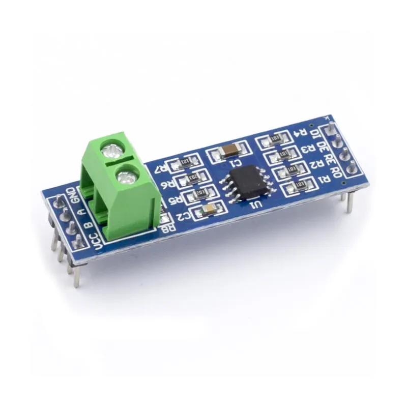
MAX485 modul s čipem MAX485 s nízkou spotřebou pro komunikaci RS-485. RS485 se používá pro sériovou komunikaci na delší vzdálenosti než přímé RS232 nebo TTL a podporuje více jednotek na stejné sběrnici.
Specifikace modulu MAX485:
– Pracuje na: 5V.
– Onboard připojení pro vodiče RS-485.
– Rozměry: 44mm x 14mm.
Rozměry
Délka: 4,39cm
Šířka: 1,41cm
Výška: 1,89cm
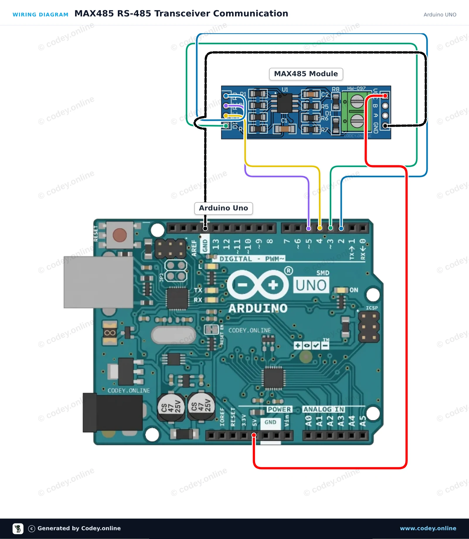
Takto připojíš MAX485 TTL na RS485 převodní modul k Arduino UNO nebo ESP32, s ukázkovým sketchem, který můžeš hned nahrát.
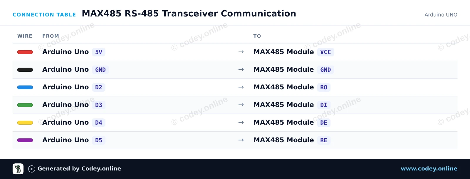
Tento obvod propojuje Arduino Uno s diferenciální sběrnicí RS-485 pomocí transceiveru MAX485. SoftwareSerial zajišťuje komunikaci s modulem, zatímco digitální piny řídí režimy vysílání a příjmu. Jakákoli zpráva zadaná do Serial Monitoru se přenáší přes RS-485 a příchozí data ze sběrnice se zobrazují na obrazovce.
/*
 * ==================================================================
 *  Generated by Codey.online  —  https://www.codey.online
 * ==================================================================
 *  Project   : MAX485 RS-485 Transceiver Communication
 *  Board     : Arduino UNO (arduino:avr:uno)
 *  Parts     : MAX485 TTL to RS485 Converter Module
 *  Libraries : none (built-in)
 *
 *  Codey Online is an AI-powered browser IDE for Arduino and ESP32.
 *  Describe your project and Codey writes the code, draws the wiring
 *  diagram and uploads it to your board, straight from the browser.
 *  This code is free to use, modify and share, without warranty.
 * ==================================================================
 */

#include <SoftwareSerial.h>

const byte PIN_RO = 2;   // Receiver Out (RX)
const byte PIN_DI = 3;   // Driver In (TX)
const byte PIN_DE = 4;   // Driver Enable (Active HIGH)
const byte PIN_RE = 5;   // Receiver Enable (Active LOW)

SoftwareSerial rs485(PIN_RO, PIN_DI);

unsigned long lastSend = 0;
int packetCount = 0;

void setTransmitMode() {
  digitalWrite(PIN_RE, HIGH); // Disable receiver
  digitalWrite(PIN_DE, HIGH); // Enable driver
  delayMicroseconds(50);
}

void setReceiveMode() {
  digitalWrite(PIN_DE, LOW);  // Disable driver
  digitalWrite(PIN_RE, LOW);  // Enable receiver
  delayMicroseconds(50);
}

void rs485Send(const String &msg) {
  setTransmitMode();
  rs485.println(msg);
  rs485.flush();
  setReceiveMode();
}

void setup() {
  pinMode(PIN_DE, OUTPUT);
  pinMode(PIN_RE, OUTPUT);
  setReceiveMode();

  Serial.begin(115200);
  rs485.begin(9600);

  Serial.println(F("MAX485 RS-485 Transceiver Demo"));
  Serial.println(F("Type a message and press Enter to send over RS-485."));
}

void loop() {
  // Forward incoming Serial Monitor input to RS-485
  if (Serial.available()) {
    String input = Serial.readStringUntil('\n');
    input.trim();
    if (input.length() > 0) {
      Serial.print(F("Sending: "));
      Serial.println(input);
      rs485Send(input);
    }
  }

  // Forward received RS-485 data to Serial Monitor
  if (rs485.available()) {
    Serial.print(F("Received: "));
    while (rs485.available()) {
      char c = (char)rs485.read();
      Serial.print(c);
      delay(2);
    }
    Serial.println();
  }

  // Automatically send a heartbeat packet every 5 seconds
  if (millis() - lastSend >= 5000) {
    lastSend = millis();
    packetCount++;
    String packet = "Ping #" + String(packetCount);
    Serial.print(F("Auto-transmitting: "));
    Serial.println(packet);
    rs485Send(packet);
  }
}Wiring diagram and example code generated by Codey.online — https://www.codey.online
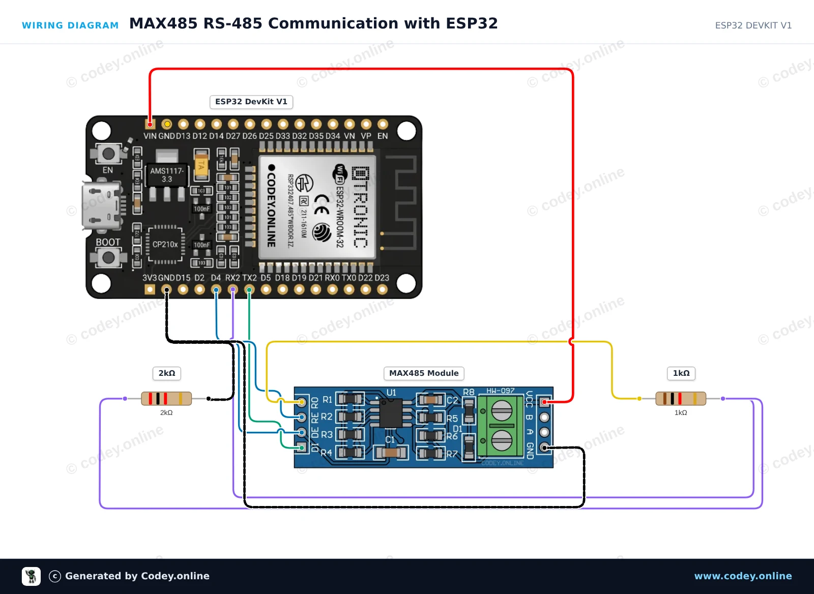
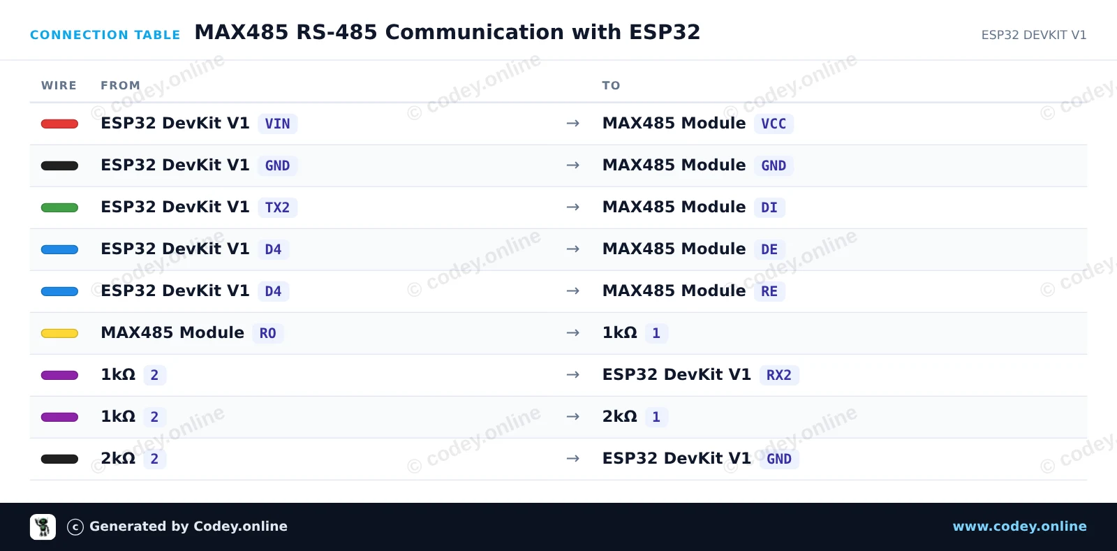
Tento projekt ukazuje, jak odesílat a přijímat data po sběrnici RS-485 pomocí modulu MAX485 a UART2 na ESP32. ESP32 nastaví piny DE/RE na HIGH, aby vysílalo periodickou heartbeat zprávu, a nastaví je na LOW, aby poslouchalo příchozí RS-485 pakety. Jednoduchý dělič napětí 1kΩ/2kΩ bezpečně sníží 5V TTL výstup (RO) modulu na 3.3V pro pin RX ESP32.
/*
 * ==================================================================
 *  Generated by Codey.online  —  https://www.codey.online
 * ==================================================================
 *  Project   : MAX485 RS-485 Communication with ESP32
 *  Board     : ESP32 DEVKIT V1 (esp32:esp32:esp32doit-devkit-v1)
 *  Parts     : MAX485 TTL to RS485 Converter Module
 *  Libraries : none (built-in)
 *
 *  Codey Online is an AI-powered browser IDE for Arduino and ESP32.
 *  Describe your project and Codey writes the code, draws the wiring
 *  diagram and uploads it to your board, straight from the browser.
 *  This code is free to use, modify and share, without warranty.
 * ==================================================================
 */

// MAX485 TTL to RS-485 transceiver demo with ESP32

const int CONTROL_PIN = 4; // Controls DE and RE (HIGH = Transmit, LOW = Receive)
const int RXD2_PIN = 16;
const int TXD2_PIN = 17;

unsigned long lastSendTime = 0;
int messageCount = 0;

void setup() {
  Serial.begin(115200);
  pinMode(CONTROL_PIN, OUTPUT);
  digitalWrite(CONTROL_PIN, LOW); // Start in receive mode

  // Initialize UART2 for RS-485 communication
  Serial2.begin(9600, SERIAL_8N1, RXD2_PIN, TXD2_PIN);

  Serial.println("RS-485 Transceiver Ready");
}

void loop() {
  // Send a message every 2 seconds
  if (millis() - lastSendTime >= 2000) {
    lastSendTime = millis();
    messageCount++;

    // Enable RS-485 transmitter
    digitalWrite(CONTROL_PIN, HIGH);
    delay(10);

    String msg = "Hello from ESP32 #" + String(messageCount);
    Serial2.println(msg);
    Serial2.flush(); // Wait until all outgoing bytes are transmitted

    // Return to receive mode
    digitalWrite(CONTROL_PIN, LOW);

    Serial.print("Sent over RS-485: ");
    Serial.println(msg);
  }

  // Check for incoming RS-485 data
  if (Serial2.available()) {
    Serial.print("Received via RS-485: ");
    while (Serial2.available()) {
      char c = (char)Serial2.read();
      Serial.print(c);
    }
    Serial.println();
  }
}Wiring diagram and example code generated by Codey.online — https://www.codey.online







 English
  Nederlands
  Frans
Frans  Deutsch
  Italiano
  Español
  Suomi
Suomi  Polski
  Dansk
Dansk  Ελληνικά
  Български
  Hrvatski
  Aileen