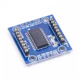
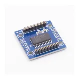
SKU: OT3643 Číslo položky: AA185 EAN: 8720618489722

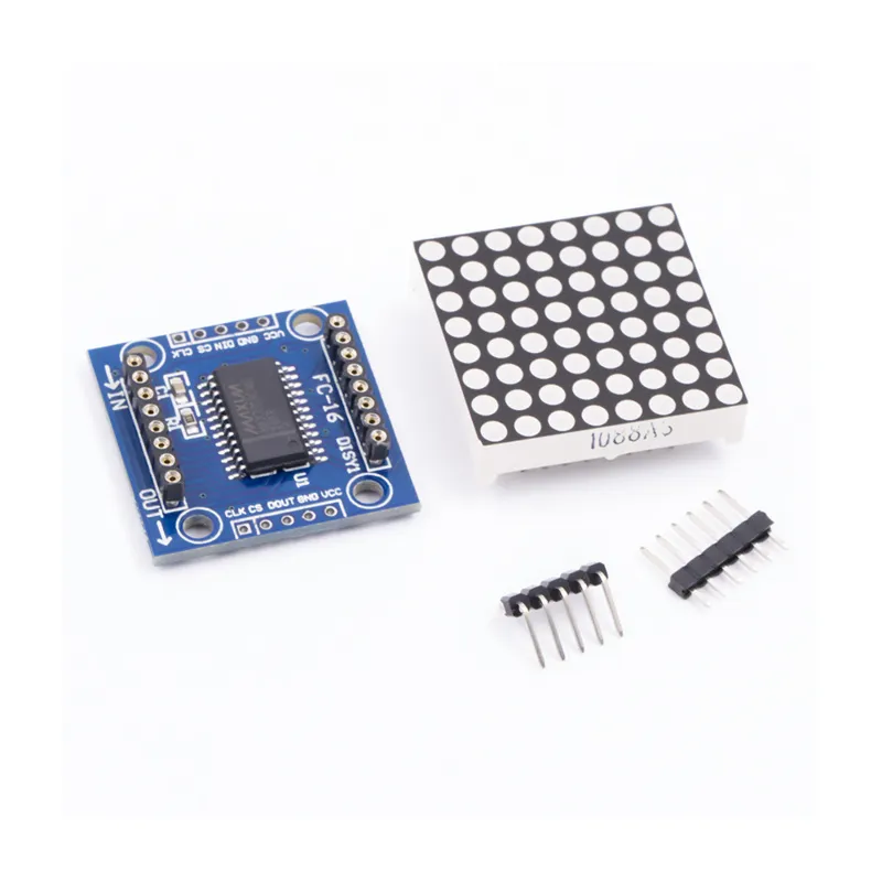
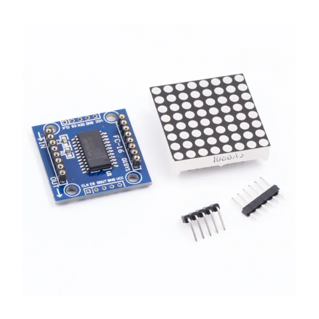
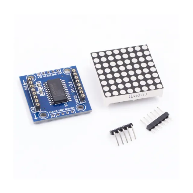
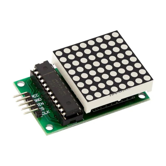
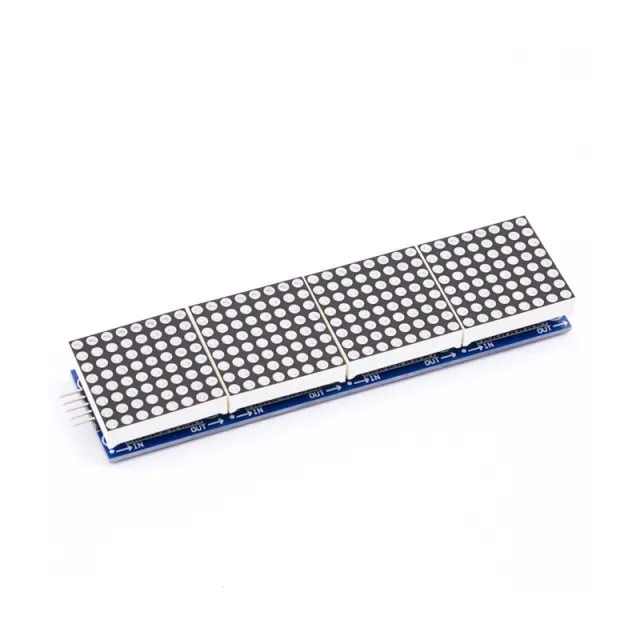
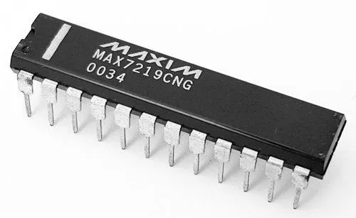
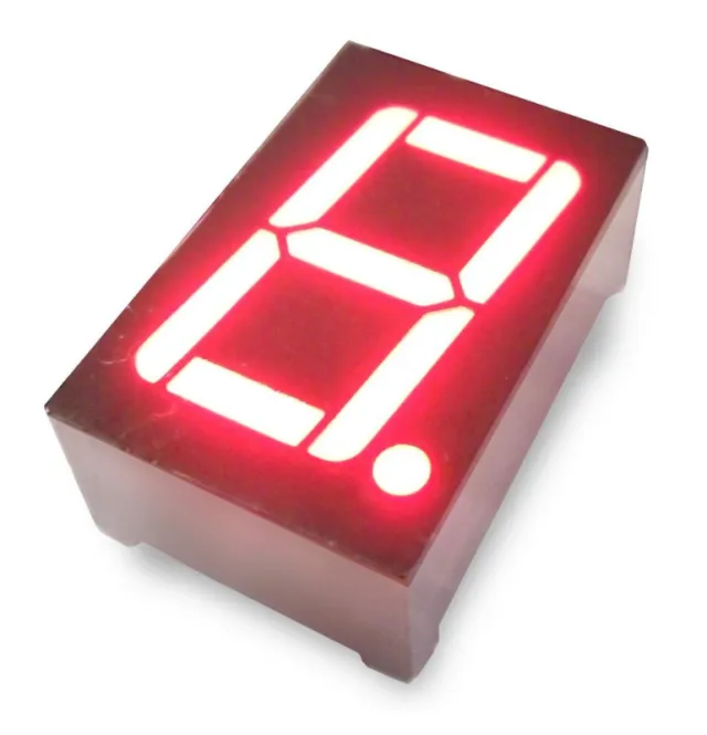
MAX7219 je IC, které se používá pro řízení LED panelů se společnou katodou, displejů se 7 segmenty a indikátorů úrovně, které komunikují přes rozhraní SPI. Tato deska má 8x8 dot matrix LED displej. Více modulů lze řetězit pomocí header propojení.
Specifikace:
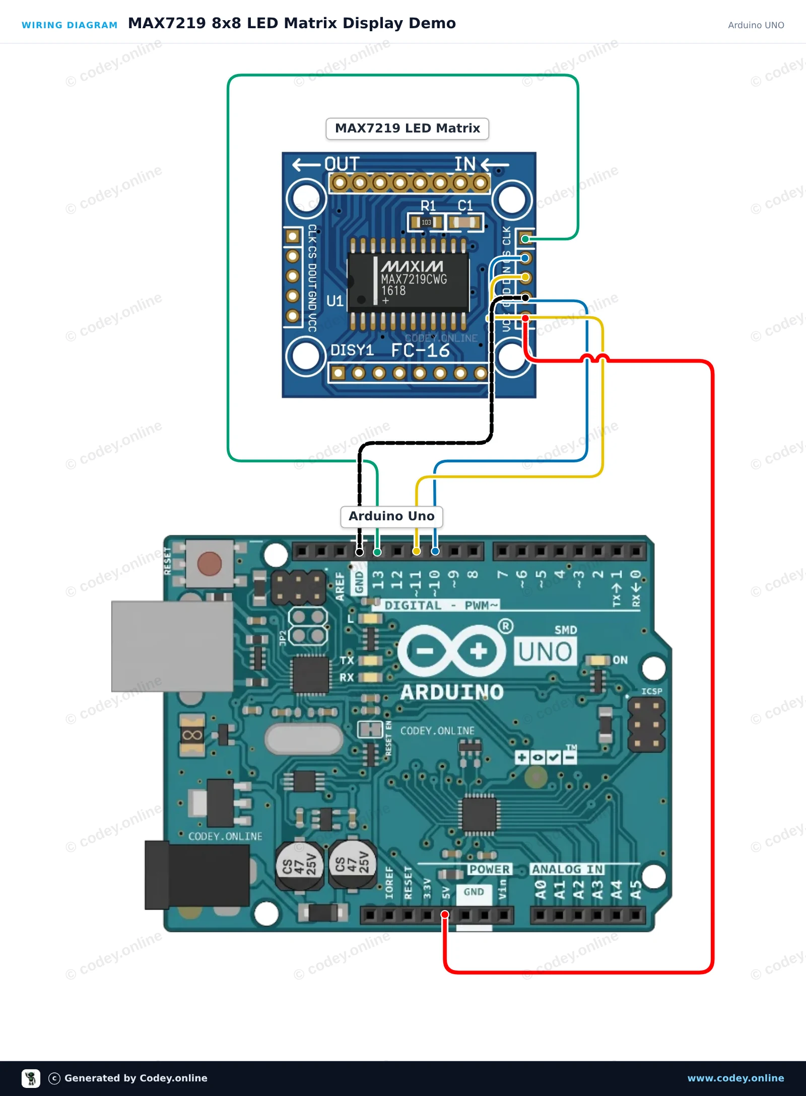
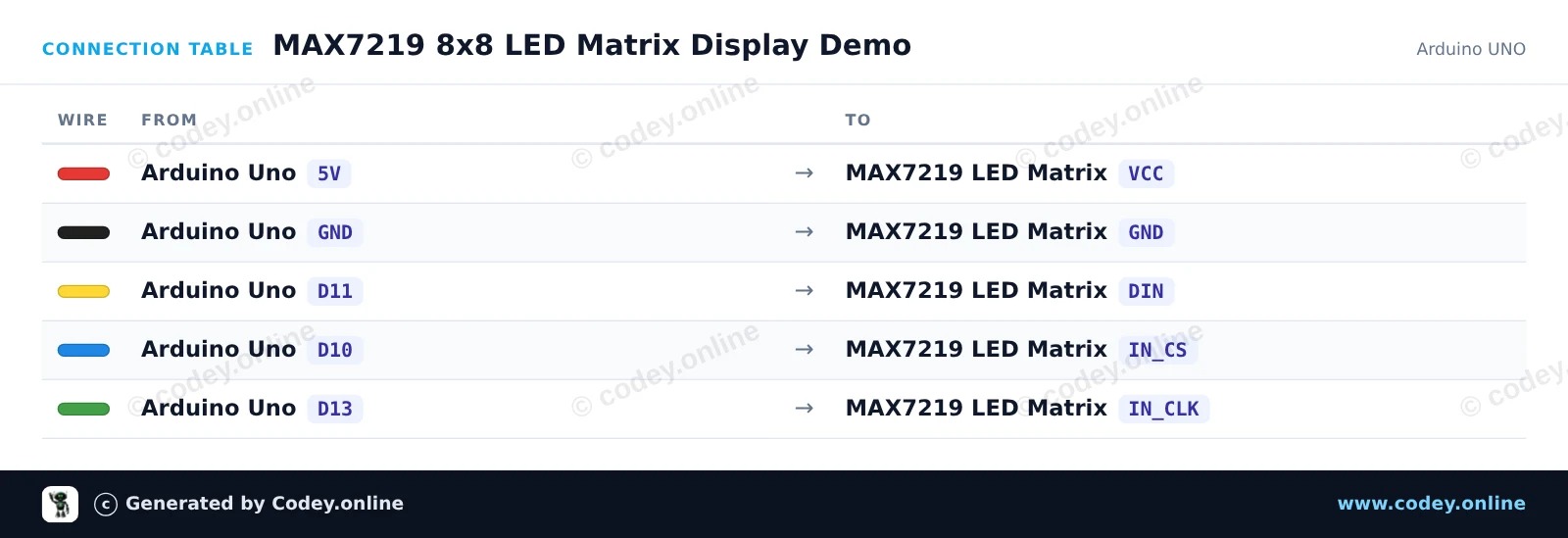
Takto připojíš LED Matrix Module MAX7219 Červený k Arduino UNO nebo ESP32, s ukázkovým sketchem, který můžeš hned nahrát.
Tento projekt ukazuje, jak ovládat 8x8 LED matici pomocí řídicího čipu MAX7219. Inicializuje displej a postupně zobrazuje smajlík, ikonu srdce a skenovací pixelový vzor.
/*
 * ==================================================================
 *  Generated by Codey.online  —  https://www.codey.online
 * ==================================================================
 *  Project   : MAX7219 8x8 LED Matrix Display Demo
 *  Board     : Arduino UNO (arduino:avr:uno)
 *  Parts     : LED Matrix Module MAX7219
 *  Libraries : LedControl 1.0.6
 *
 *  Codey Online is an AI-powered browser IDE for Arduino and ESP32.
 *  Describe your project and Codey writes the code, draws the wiring
 *  diagram and uploads it to your board, straight from the browser.
 *  This code is free to use, modify and share, without warranty.
 * ==================================================================
 */

#include <LedControl.h>

const int DIN_PIN = 11;
const int CS_PIN  = 10;
const int CLK_PIN = 13;

LedControl lc = LedControl(DIN_PIN, CLK_PIN, CS_PIN, 1);

// 8x8 bitmap patterns
const byte SMILEY[8] = {
  0b00111100,
  0b01000010,
  0b10100101,
  0b10000001,
  0b10100101,
  0b10011001,
  0b01000010,
  0b00111100
};

const byte HEART[8] = {
  0b00000000,
  0b01100110,
  0b11111111,
  0b11111111,
  0b01111110,
  0b00111100,
  0b00011000,
  0b00000000
};

void drawPattern(const byte pattern[8]) {
  for (int row = 0; row < 8; row++) {
    lc.setRow(0, row, pattern[row]);
  }
}

void setup() {
  Serial.begin(115200);
  Serial.println(F("MAX7219 LED Matrix Demo"));

  lc.shutdown(0, false);  // Wake up display
  lc.setIntensity(0, 5);  // Brightness (0-15)
  lc.clearDisplay(0);
}

void loop() {
  // Show smiley face
  drawPattern(SMILEY);
  delay(2000);

  // Show heart
  drawPattern(HEART);
  delay(2000);

  // Clear display
  lc.clearDisplay(0);
  delay(500);

  // Scan a single pixel across all rows and columns
  for (int row = 0; row < 8; row++) {
    for (int col = 0; col < 8; col++) {
      lc.setLed(0, row, col, true);
      delay(30);
      lc.setLed(0, row, col, false);
    }
  }
  delay(500);
}Potřebné knihovny: LedControl 1.0.6
Wiring diagram and example code generated by Codey.online — https://www.codey.online
Tento projekt ukazuje, jak ovládat 8x8 LED maticový displej MAX7219 pomocí hardwarového rozhraní SPI ESP32. Sketch inicializuje registry displeje a střídá zobrazení ikony srdce a smajlíka.
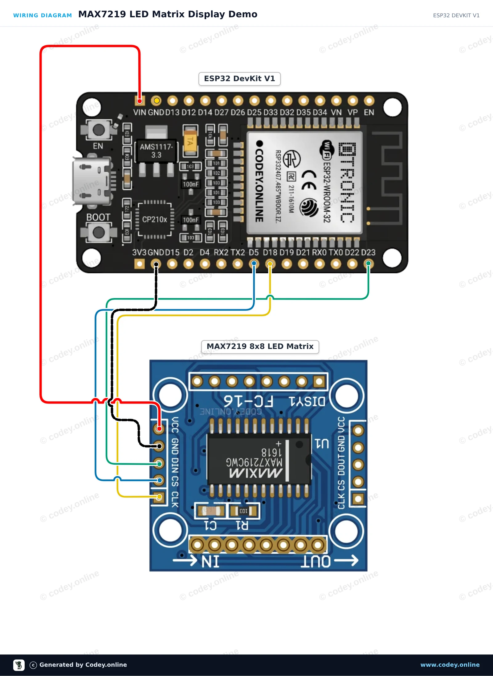
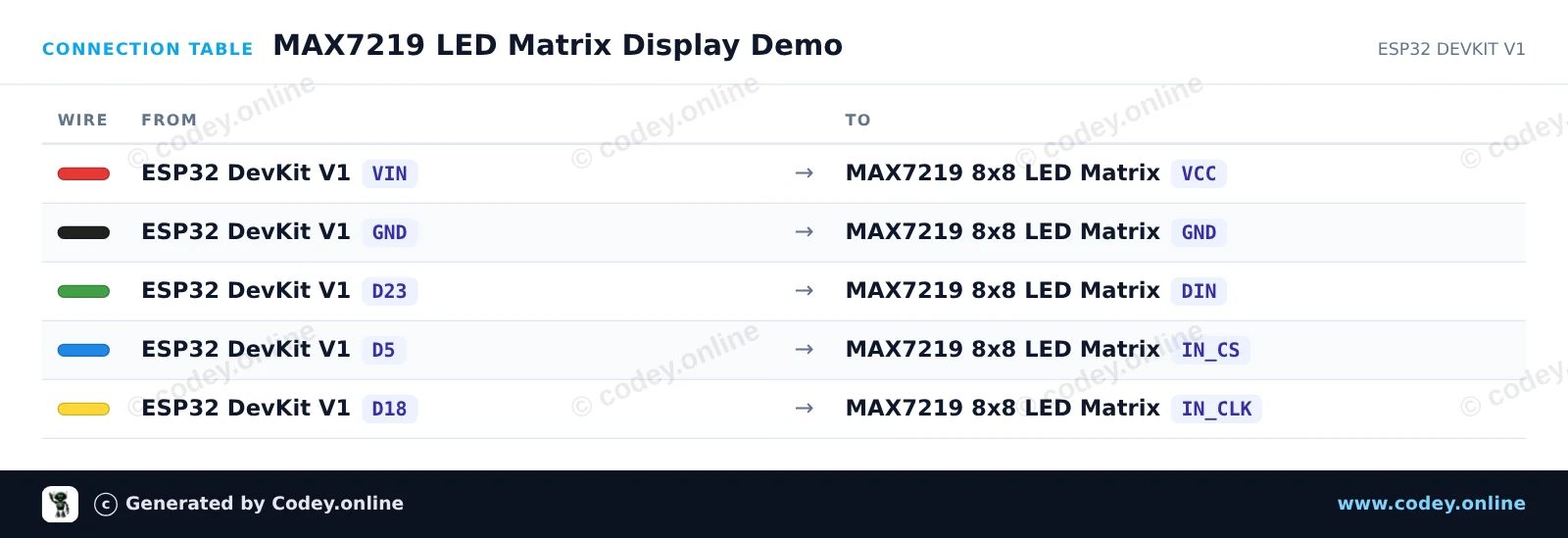
/*
 * ==================================================================
 *  Generated by Codey.online  —  https://www.codey.online
 * ==================================================================
 *  Project   : MAX7219 LED Matrix Display Demo
 *  Board     : ESP32 DEVKIT V1 (esp32:esp32:esp32doit-devkit-v1)
 *  Parts     : LED Matrix Module MAX7219
 *  Libraries : none (built-in)
 *
 *  Codey Online is an AI-powered browser IDE for Arduino and ESP32.
 *  Describe your project and Codey writes the code, draws the wiring
 *  diagram and uploads it to your board, straight from the browser.
 *  This code is free to use, modify and share, without warranty.
 * ==================================================================
 */

#include <SPI.h>

const int PIN_CS = 5;

// MAX7219 register addresses
const byte REG_NOOP        = 0x00;
const byte REG_DIGIT0      = 0x01;
const byte REG_DECODEMODE  = 0x09;
const byte REG_INTENSITY   = 0x0A;
const byte REG_SCANLIMIT   = 0x0B;
const byte REG_SHUTDOWN    = 0x0C;
const byte REG_DISPLAYTEST = 0x0F;

const byte heart[8] = {
  0b00000000,
  0b01100110,
  0b11111111,
  0b11111111,
  0b11111111,
  0b01111110,
  0b00111100,
  0b00011000
};

const byte smile[8] = {
  0b00111100,
  0b01000010,
  0b10100101,
  0b10000001,
  0b10100101,
  0b10011001,
  0b01000010,
  0b00111100
};

void writeRegister(byte reg, byte data) {
  digitalWrite(PIN_CS, LOW);
  SPI.transfer(reg);
  SPI.transfer(data);
  digitalWrite(PIN_CS, HIGH);
}

void showBitmap(const byte bitmap[8]) {
  for (byte i = 0; i < 8; i++) {
    writeRegister(REG_DIGIT0 + i, bitmap[i]);
  }
}

void setup() {
  Serial.begin(115200);
  Serial.println("MAX7219 LED Matrix Demo Started");

  pinMode(PIN_CS, OUTPUT);
  digitalWrite(PIN_CS, HIGH);

  SPI.begin();

  writeRegister(REG_DISPLAYTEST, 0x00); // Normal operation
  writeRegister(REG_SCANLIMIT, 0x07);   // Display all 8 rows
  writeRegister(REG_DECODEMODE, 0x00);  // No BCD decoding (raw matrix)
  writeRegister(REG_INTENSITY, 0x04);   // Brightness (0x00 to 0x0F)
  writeRegister(REG_SHUTDOWN, 0x01);    // Wake up from shutdown
}

void loop() {
  showBitmap(heart);
  delay(1000);

  showBitmap(smile);
  delay(1000);
}Wiring diagram and example code generated by Codey.online — https://www.codey.online






 English
  Nederlands
  Frans
Frans  Deutsch
  Italiano
  Español
  Suomi
Suomi  Polski
  Dansk
Dansk  Ελληνικά
  Български
  Hrvatski
  Aileen